NOTICE: These are tech pages explaining how I did these mods to my bike. In almost every case - |
|
|
Rewire Interstate Trunk Run & Brake Lights into Run, Brake & Turn
Thanks to Mark Smith for his elegant contribution to the circuit design
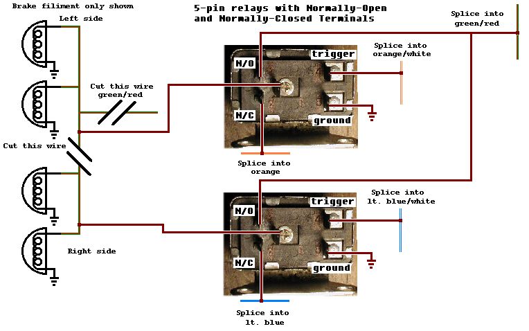
- 2 5-pin relays with Normally-Open & Normally-Closed terminals, available at any auto parts store (print & take this with you if you're not sure what to get)
- spool of 18 ga wire
- heat shrink tubing
- female spade connectors
- wire ties
- Phillips screwdriver
- soldering equipment
- heat gun or hair dryer or bic lighter
- needlenose pliers
- 1/4" drive metric socket set and 6" extension
Rationale
The Turn signals on the Valk Interstate are too low. But those four lights on the trunk are plenty visible. Why aren't they also turn signals? Now they can be.
This is an easy, inexpensive, and simple mod. Well worth the trouble.
Cost
About $20 if you have soldering tools.
Time
2-4 hours.
Materials
Tools
Process
The Valk has an unusual design for the turn signal lights in front. The turn switch is actually two switches in one - the second part of the switch controls
the power to the marker light filiments - when the turn signal is activated, it interrupts the power for that filiment on that side to maximize contrast. How
convenient! We can use that to control relays for seperating the circuits in back.
 |
Be sure to solder all connections, and use heat shrink tubing - that is MUCH more reliable than crimp connections.
Seperate the left and right pairs of lights in the trunk, brake circuit only.
NOTE: The diagram indicates all lights in back are dual filiment. Actually only
two are 1157-type bulbs, with the other two being single filiment, I believe running lights. You will have to change the sockets and bulbs of the single
filiment pair if you want all four to be brake & turn lights. Otherwise this diagram applies to the two 1157 sockets, not the other two.
In the looms up front (in the headlight on a standard) locate the light blue/white wire (right running light) and the orange/white wire (left running light). They will be between the left handle bar and the turn signals. Splice into them, and run the wires along the frame under the tank using wire ties, to where you want the relays (probably under the seat?). Mount the two relays. The relays used here have one terminal each for Trigger (pin4), Load (pin1), and Ground(pin5). They also have two "battery" terminals (that is, we will use them for the power side of the switch, they are usually used on the load side, but the relay doesn't care which way the power goes though the switch). Pin2 is normally closed, that is, 2 has continuity with Load(pin1) without power at the trigger(pin4). Pin 3 is normally open (no continuity with Load without power at the trigger). Of course when the power is applied to the trigger their state is reversed. Clear as mud?
Connect the wires you ran to the triggers (pin4) of the relays (one wire to each relay trigger). Connect the brake wire (green/red) under the seat (it's in the loom that runs up the fender under the seat) to the Normally Open "battery" terminal(pin3) on both relays. Connect the right and left turn lines to the Normally Closed "battery" terminals(pin2 ). Right turn line is light blue. Left turn is orange. They are also in that same loom under the seat. Switched output leads (Load) go to the brake light wires you run to the left and right light pairs, brake leads.
You see what you're doing. Using the switched running lights in front to allow the brake lights in back to operate normally (relays active) or disabled
on the side you're turning to (relay triggers off), with the Normally Closed side of the relay substituting the turn signal into the brake lines.

All technical mods described here are merely reports of what I've done. You may attempt to replicate them at your own discretion and risk if you choose. Horseapple Ranch, LLC and Mark Tobias will in no way be responsible for the results of your attempting to perform these mods on any motorcycle, regardless of the outcome.
All content on www.horseapple.com copyright 1999-2006 Mark Tobias except "Riders Say", "Dyno Day", Vallejo and Shop Manual and Alternator Review pages, and SWF and MP-3 files and
their graphic icons, and any content specifically attributed to another author.
All rights reserved.