NOTICE: These are tech pages explaining how I did these mods to my bike. In almost every case - |
Install VTX Signal Pods as Run, Turn, & Stop with Night Lights Switch
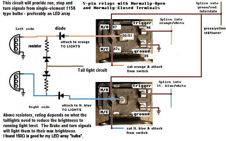
Rationale Because they make you more visible. OK, because they look good - and no one else has them on a Valk (Except me). And they aren't likely to - these suckers are SPENDY. Secondly, this mod fixes the unreadable instruments at dusk problem. Cost If you use VTX pods all around, about $300. If you just change the back pods to Honda fronts (to get dual filiments), then about $60 using non-Honda pods. You can find non-Honda brand pods for about half the price - my dealer, Aurora Honda (303-341-7200) carries them. BTW, they come from the same place - the casting marks inside in the plastic are identical, and I could find no other differences when comparing them side by side. Time All day. Materials - much less if you just replace the rear pods with fronts. Also, this can be done using single-filiment pods, which is what the VTX pods are. I haven't tested this and found what ohm resistors are needed to cut the light in half for the running light function. But that wouldn't be difficult, especially using a variable resistor (aka POT) from Radio shack, in the range of say 0-1000 ohms. Put it in place of the resistor, turn the pot dial until you like the brightness, then measure what resistance you used with a ohm meter. Then go buy resistors that size. You will also need diodes to prevent the backflow of running-light current into the brake light circuit. See the diagram below.
Tools I used - much less if you just replace the rear pods
Process Overview: There isn't enough light on the back of the Valk standard & tourer at night. Daytime, the running lights won't help, and the rear light pods won't work long in the heat of the day with running lights on, without melting. I know that because I melted two pairs of the Valk front pods by installing them in the back, behind the saddlebags, and having the running lights on all the time. It finally sunk in and I switched them off in the daytime. At night, the ambient air is cool enough, and the sun isn't contributing to their heat - and they never melted again. These light pods are EXPENSIVE. So we don't want to risk melting them by having the running lights on in the daytime when they don't help visibility anyway. The brake and turn signal filiments are only on momentarily, so melting isn't a concern. Look at the wiring diagram. Look at the brown/white circuit. It powers the
instrument lights, tail, license, and front markers. We will use it to power the rear markers too. Notice there is nothing on the brown/white circuit that needs to be on
in the daytime, except the one brown wire that powers the front marker lights (needed for our circuit). Notice in particular that the instrument illumination is on
the same circuit. If you put a switch on this circuit and call it the "night lights" switch, you will be reminded to turn it on when you can't see the instruments after
dark. BONUS - This is another mod you will find on my tech tip pages - it's a good idea to switch the instrument lights off in the daytime, because then there is plenty
of contrast at dusk to see the numerals - they no longer disappear due to the light from inside matching the skylight reflected off the bezel - the numerals appear black and you can see them
until it's time to turn on the Night Lights! These light pods look sharp - they are more pointy than the Valk pods, they have
clear lenses, and they have clearly visible facets on the reflector - makes the light inside look like the current style for upscale cars - and looks a bit like an expensive
LED light fixture. However, Honda made this pod with a single filiment bulb - including the ones for the front (unlike the Valk pods) - and uses a sophisticated
circuit to change the brightness of that one filiment. I was working on my design of such a circuit, when I realized it was much easier and cheaper to just replace the
sockets inside with dual filiment sockets compatible with 1157 bulbs. So you need to use a Dremel with cutting wheel to cut up the existing single filiment socket to
remove it. I also used a belt sander on the back rim of the hole until it was flush with the smaller I.D. hole to reduce the depth of the socket hole in the reflector to
be compatible with the spring-mounted sockets I had bought. It was the right power tool, but you can also do it with a file, or a dremel with a burr (rotary file) or the like.
This mod can be done much cheaper using Honda Valkyrie front pods. Replace the amber lenses with clear ones from Auto Zone, and use the red krypton 1157 bulbs. Now, the details: Switching the brown/white circuit: We want to switch everything on the brown/white circuit except the brown power wire to the front marker lights - we
need this part of the circuit to control the relays. There is a 9-pin miniconnector inside the headlight nacelle, black in color, that connects the right handlebar switch
loom to the bike circuits. On the "bike side" of the connector is a brown/white striped wire. Right next to it on the connector is a brown/blue striped wire. Follow
the brown/white wire until you find where it connects to a brown only wire. Attach a jumper wire from the Brown/blue wire to the brown only wire using the soldering
equipment and heat shrink tubing. Sever the connection between the brown and brown/white wire. Somewhere on the brown/white wire, after it leaves the
connector but before it connects to any other wires, install the toggle switch to break the circuit, and place the toggle where you can reach it easily with gloved hands. This will be the "night switch". Replace the single filiment sockets in the pods with the dual filiment sockets. The VTX light pods phsically attach the same as the Valk pods do. No mods needed there. If you want the front marker lights on all the time, except when the turn signal on that side is activated, connect the orange/white (left) and lt. blue/white (rt.) wires to the circuits the same as the stock Valk pods, to the orange/white wire or the light blue/white wire depending on the side. As for me, I prefer to have the front pods on the night circuit, so the running filiments are connected to the brown/white circuit instead of the front marker circuits. Connect the green (ground) wires to the green ground wires in the headlight, and the wire you added to the orange or lt. blue turn signal circuits as appropriate. In back, connect the running light wires to the brown/white circuit, the green ground wires to the green wires in the bike loom, and the orange and blue wires to their corresponding colors in the bike loom. The Valk has an unusual design for the turn signal lights in front. The turn switch is actually two switches in one - the second part of the switch controls the power to the marker light filiments - when the turn signal is activated, it interrupts the power for that filiment on that side to maximize contrast. How convenient! We can use that to control relays for seperating the circuits in back. This is the diagram for the Interstate Turn signals mod
slightly modified - we will use the same circuit to set up the rear markers as run, turn and stop lights. Just replace the green/red (Interstate) brake circuit reference with green/yellow
(standard/tourer). NOTE 5/17/08: The circuit below shows how to do this with 1156 pods. This circuit will work best with LED array taillights. I have not tested it with filiment lights, which will certainly change the resistors rating - which needs to be adjusted anyway depending on the requirements of your LED arrays. If you do this to 1157-equipped lights - you would not add the diodes and resistors and tail light circuit connection, to the left of the relays, in the diagram. The tail light circuit would instead be connected to the running light pin of the 1157 sockets.
]
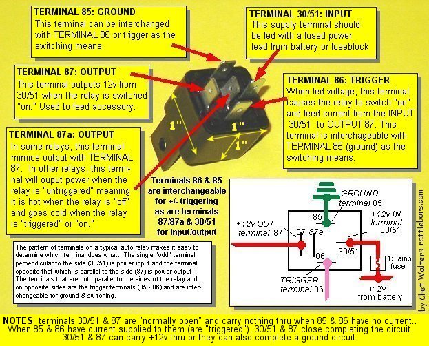
Here's a diagram of another commonly found auto relay, and the type I used in this particular project. Thanks to Chet Walters & his great graphics for the diagram.
Whatever type you get, be sure the output pins are 87 (normally off) and 87a (normally closed), not two 87's (normally off). The latter type relay is used
specifically for wiring something like two spots, to save the installer from making a Y-harness. That type relay looks the same except for it's wiring diagram but it won't work in this circuit.
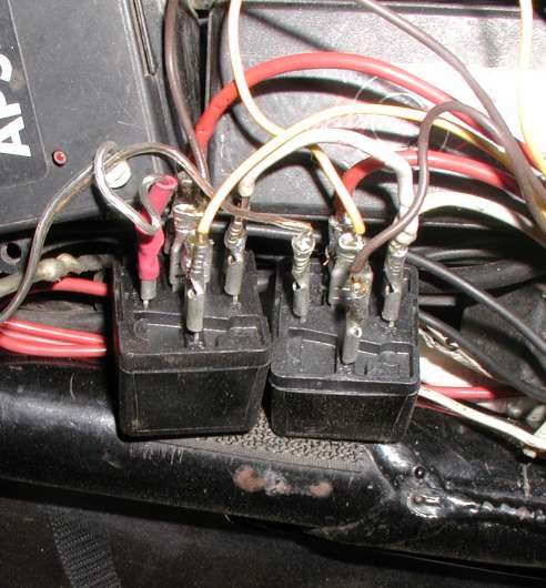
Here's what my relay install looked like before I loomed the wires.
In the looms up front (in the headlight on a standard) locate the light blue/white wire (right running light) and the orange/white wire (left running light) inside the headlight. They are inside their own little loom. Splice into them, and run the wires along the frame under the tank using wire ties, to where you want the relays (probably under the seat?). Mount the two relays. The relays used here have one terminal each for Trigger (pin4, 86), Load (pin1, 30/51), and Ground(pin5, 85). They also have two "battery" terminals 87 & 87a (that is, we will use them for the power side of the switch, they are usually used on the load side, but the relay doesn't care which way the power goes though the switch). Pin2 (87a) is normally closed, that is, 2 has continuity with Load(pin1, 30/51) without power at the trigger(pin4, 86). Pin 3 (87) is normally open (no continuity with Load without power at the trigger). Of course when the power is applied to the trigger their state is reversed. Clear as mud? Connect the wires you ran from the loom in the headlight to the triggers (pin4, 86) of the relays (one wire to each relay trigger). Connect the brake wire (green/red -I/S, green/yellow std, tourer) FROM THE BRAKE SWITCH under the seat (it's in the loom that runs up the fender under the seat) to the Normally Open "battery" terminal(pin3, 87) on both relays. Make a "Y" harness with a screw terminal on one end and the female spade connectors on the other 2 ends and connect them to ground on the relays (pin5, 85) and the screw terminal to your favorite underseat ground (I drilled and tapped a hole for the ground). Connect the right and left turn signal lines in the bike loom (cut the circuits, so the relay switches them) FROM THE TURN SIGNAL SWITCH to the Normally Closed "battery" terminals(pin2, 87a). Right turn line is light blue. Left turn is orange. They are also in that same loom under the seat. Switched output leads (Load) go to the corresponding turn signal lines TO THE LIGHTS. You see what you're doing. Using the switched marker light circuits in front to select the brake lights in back to operate normally (relays active) or disabled on the side you're turning to (relay triggers off), with the Normally Closed side of the relay substituting the turn signal into the brake lines. Debugging - Problems I had One of my deep-blue bulbs, the pins were incorrect in relation to the contacts. Only the brake filiment would light with either circuit. I'll get it replaced, I still want to have deep blue in back when the mood hits. Meanwhile it's xenon red. EDIT 6/06: I changed to the red LED cluster 1157 bulbs at Auto Zone. They didn't dim the running light brightness enough. I added a resistor to the running light feed of each pod to increase the difference when the brakes are applied. 220ohms results in a plenty bright running light with these LED "bulbs", and easily twice as bright when the brake / turn signal is activated. Resistors are available at Radio Shack.DO pay attention to the alignment of the filiments in relation to the reflector. It makes a big difference in the light output.
I had to re-ground the green circuit, both front and rear as the Honda ground had too much resistance and apparently the Kisan taillight modulator modulates the
ground connection. I will seperate those circuits later by adding a seperate ground wire to the back but I wanted to get this done so for now I have shut down the
taillight modulator by jumpering the ground that otherwise passes through it. I have the circuit board type modulator, not the one in the bulb socket.
One of the relays was bad - wouldn't trigger. Well it seems like a hassle, but it sure looks good. I have all red lights in back now, and the rear turn signals also function as marker and brake lights. With those very stylish clear lenses I can change bulb colors easily - I have a set of deep blue lights I'd like to install until an LEO yells at me... Somehow I'm going to add the deep purple glow to the red in the rear; havn't really figured that out yet. What I'd like to do is have something like a neon black light inside the pod as well, or if I can find LED's in blacklight wavelength.
|


All technical mods described here are merely reports of what I've done. You may attempt to replicate them at your own discretion and risk if you choose. Horseapple Ranch, LLC and Mark Tobias will in no way be responsible for the results of your attempting to perform these mods on any motorcycle, regardless of the outcome.
All content on www.horseapple.com copyright 1999-2006 Mark Tobias except "Riders Say", "Dyno Day", Vallejo and Shop Manual and Alternator Review pages, and SWF and MP-3 files and
their graphic icons, and any content specifically attributed to another author.
All rights reserved.